- #PROGRESSIVE DYNAMICS POWER CONVERTER WIRING DIAGRAM PD764Q INSTALL#
- #PROGRESSIVE DYNAMICS POWER CONVERTER WIRING DIAGRAM PD764Q FREE#
#PROGRESSIVE DYNAMICS POWER CONVERTER WIRING DIAGRAM PD764Q FREE#
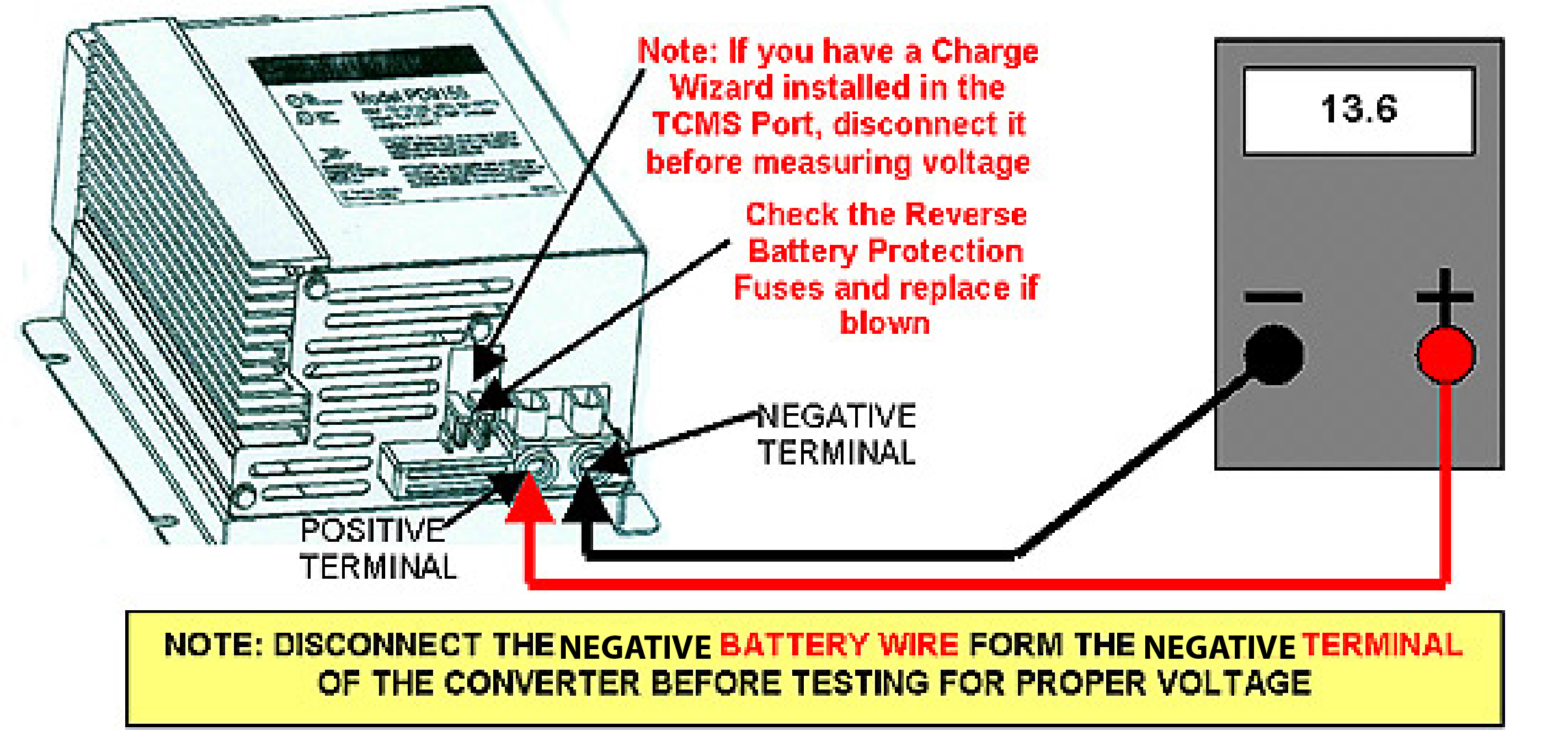
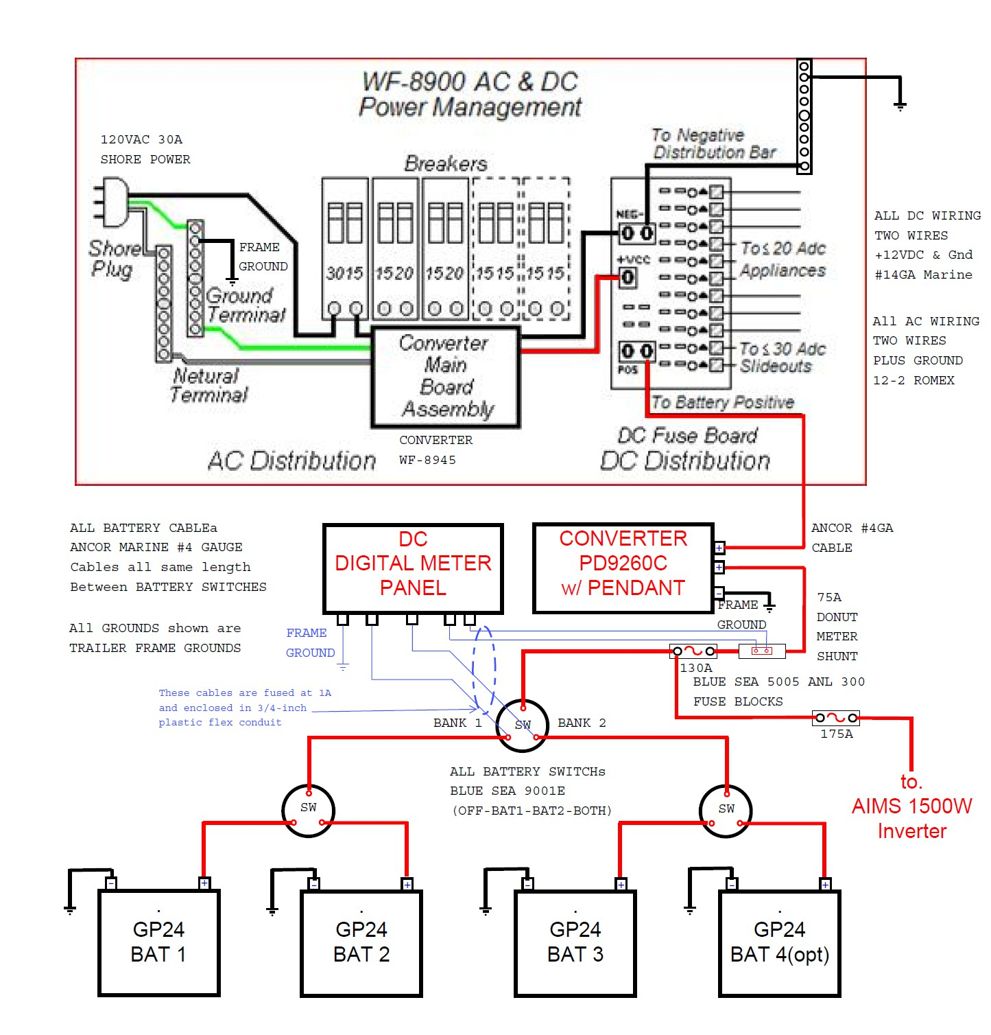
When changing the voltage selector switch from 240v to 120v ensure that the power supply is turned off.Rv Converter Wiring Schematic | Free Wiring Diagram. The following diagrams illustrate typical wiring conventions for the electrical service types supported by the different ion8650 meter form factors. The Current Wire Connects To X1 On The Ct.Ĭonnect the phase of the load to terminal l and neutral of the load to. Now, if your wattmeter having four terminals and identified as m, l, c, v then the following connection diagram should be followed. The instrument should be connected as shown in one of the diagrams as appropriate for 3 phase 3 wire and 3 phase 4 wire. It Shows How The Electrical Wires Are Interconnected And Can Also Show Where Fixtures And Components May Be Connected To The System.

Includes single phase, 2 phase supply, 3 phase supply, multiple installations, distributed generation/alternative energy and typical equipment dimensions. Assortment of volt amp meter wiring diagram. Dc 100V 10A 50A 100A Voltmeter Ammeter Led Dual Digital Volt Meter P5N4 Amp G2P6 Sho Polska. Wire size code/wire color 5.5: After completing all electrical wiring, mounting and installation steps, refer to "step 10: Print the wiring diagram off and use highlighters to be able to trace the routine. If You Want To Use This Meter, You Need To Purchase A 100A/75Mv Shunt. Use phasor diagrams to verify wiring" for details on meter operation for different systems and volts. Ammeter voltmeter selector switch avs wiring diagrams tm 55 1930 209 14p 9 4 262.
#PROGRESSIVE DYNAMICS POWER CONVERTER WIRING DIAGRAM PD764Q INSTALL#
If it is oversized, install a 1 ampere fuse in the hot lead near the source. Vacant or buck circuit (module) negative red line (thin): The 16 Awg Meter Sensing Wires. Source: From there all electrical loads should come out the other side of the terminal block. From there all electrical loads should come out the other side of the terminal block. The smaller black line connects to the voltage terminal in the form 9s meter socket and the thicker black line comes from the ct and connects to the current terminal. Source: Now, if your wattmeter having four terminals and identified as m, l, c, v then the following connection diagram should be followed. 3 phase energy meter single ct connection. Source: Calibration the voltmeter is calibrated at the factory and recalibration should never be necessary. Meter wiring diagrams for low voltage meter stations for in whangarei and kaipara. Source: Print the wiring diagram off and use highlighters to be able to trace the routine. If you want to use this meter, you need to purchase a 100a/75mv shunt. The voltage wire connects directly to the service wire in this example. 1 run a 10 wire from the bat terminal on the alternator to the ammeter. It shows how the electrical wires are interconnected and can also show where fixtures and components may be connected to the system. Power supply+ black line (thick): Source: Source: Vacant or buck circuit (module) negative red line (thin): Com, common measuring red line (thick): Source: In the center of this diagram following the blue wire again this is an either or connection. Here is the wiring instructions for the dc 100v 10a meter: Source: Source: ġ run a 10 wire from the bat terminal on the alternator to the ammeter. In the diagram above, the wire colours shown in brackets refer to model tc0002.

Source: It shows how the electrical wires are interconnected and can also show where fixtures and components may be connected to the system. And then wiring it according to the wiring diagram we sent to you before. Com, common measuring red line (thick): Source: In the diagram above, the wire colours shown in brackets refer to model tc0002.

Connect phase to terminal m and neutral to terminal v. Use one of the wires that you found in the wiring harness and cut it between the steering column and connector in the dash. Pw+, measuring terminal voltage input positive yellow line (thick): When you measure the voltage between these 2 wires you will get 120 volts, or 230 volts for those systems not in the u.s. Vacant or buck circuit (module) negative red line (thin): Source: You will have 1 hot wire (commonly black or red) and a neutral wire (usually white). Progressive Dynamics Power Converter Wiring Diagram from 8 mm2 no mark wire size: Meter wiring diagrams for low voltage meter stations for in whangarei and kaipara. As you see in the above connection diagram, first make a short between m and c terminal. You can connect the wire to the left center terminal or the bottom center terminal.


 0 kommentar(er)
